
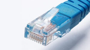
In the world of networking, the RJ45 connector has become synonymous with wired Ethernet connections. This small but powerful connector plays a crucial role in ensuring secure and reliable data transmission in various networking applications. In this article, we will explore the ins and outs of RJ45 connectors, including their anatomy, types, termination methods, and best practices for installation.
1. Anatomy of an RJ45 Connector:
An RJ45 connector is a standardized connector primarily used for Ethernet connections. It consists of a plastic body housing eight pins or conductors, which align with the eight wires inside a twisted pair cable. The connector features a latch that helps secure the connection and prevent accidental disconnections.
2. Types of RJ45 Connectors:
a. Unshielded RJ45 Connectors (UTP): These connectors are commonly used with unshielded twisted pair (UTP) cables, which are the most prevalent type of Ethernet cables. UTP RJ45 connectors are cost-effective and suitable for most residential and small business applications.
b. Shielded RJ45 Connectors (STP): Shielded RJ45 connectors are designed for use with shielded twisted pair (STP) cables. They provide better protection against electromagnetic interference (EMI) and are ideal for environments with high levels of electrical noise.
3. Termination Methods:
a. Punch-Down: Punch-down termination is a widely used method for connecting wires to an RJ45 connector. It involves using a punch-down tool to press the individual wires into the corresponding slots or terminals within the connector. This method provides reliable and secure connections.
b. Crimping: Crimping is another popular termination method where the wires are inserted into the connector, and a crimping tool is used to secure the connector onto the cable. This method is commonly used for field termination or when making custom-length cables.
4. Best Practices for RJ45 Connector Installation:
a. Cable Preparation: Ensure the cable is properly stripped, and the wires are untangled and aligned in the correct order. Proper cable preparation ensures accurate termination and optimal performance.
b. Pin Configuration: Follow the TIA/EIA-568 wiring standard (such as T568A or T568B) for pin configurations to maintain consistency and compatibility with other networking equipment.
c. Consistent Wiring: Maintain consistent wire arrangement and length to minimize crosstalk and ensure reliable data transmission.
d. Connector Orientation: Make sure the connector is oriented correctly before termination to ensure proper alignment of the pins and a secure connection.
e. Test and Verify: After termination, use a cable tester to verify the continuity and integrity of the connection. Testing helps identify any wiring errors or faults that could impact network performance.
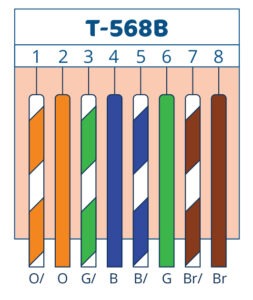
T568B is one of the two commonly used wiring standards for the pin configuration of RJ45 connectors in Ethernet networks. It defines the arrangement of the eight wires within a twisted pair cable when terminating them into an RJ45 connector. The T568B standard specifies the following pin assignments:
Pin 1: White/Orange
Pin 2: Orange
Pin 3: White/Green
Pin 4: Blue
Pin 5: White/Blue
Pin 6: Green
Pin 7: White/Brown
Pin 8: Brown
The T568B standard is widely used in North America and is the default wiring scheme for Ethernet cables in many applications, including residential and commercial networking. It provides a consistent and universal pinout configuration, ensuring compatibility between networking devices and equipment.
When terminating an RJ45 connector using the T568B standard, the wires are aligned and inserted into the corresponding slots or terminals of the connector, following the specified color-coding sequence. Proper adherence to the T568B wiring standard ensures that the wires are correctly paired and connected to the corresponding pins on both ends of the Ethernet cable, allowing for reliable data transmission and compatibility with other networking components.
It is important to note that while T568B is widely used, there is an alternative wiring standard called T568A, which has a slightly different pin configuration. The main difference between T568A and T568B lies in the arrangement of the green and orange wire pairs. However, as long as both ends of the cable are terminated using the same wiring standard (either T568A or T568B), the Ethernet connection will function correctly.
When working on a network installation or repair, it is essential to be aware of the wiring standard being used and maintain consistency throughout the network to ensure proper connectivity and avoid any potential wiring conflicts.
Conclusion:
RJ45 connectors are the backbone of Ethernet connectivity, enabling reliable data transmission in a wide range of networking applications. Understanding the anatomy, types, and termination methods of RJ45 connectors is essential for successful installations and maintaining high-performance networks. By following best practices for cable preparation, termination, and testing, you can ensure secure and robust connections, empowering your network infrastructure with the power of RJ45 connectors.
